
We have a passion for unconventional solutions that bring your vision to life.
Cleanroom airflow is the foundation of effective contamination control in controlled environments. A well-designed cleanroom airflow layout ensures that airborne particles are continuously diluted, removed, and directed away from critical processes. Without optimized cleanroom airflow, even the most advanced filtration systems cannot fully protect sensitive products or manufacturing operations.
In pharmaceutical, electronics, and healthcare facilities, cleanroom airflow design directly influences product quality, regulatory compliance, and long-term operational efficiency. When developing a contamination control strategy, cleanroom airflow should be treated as the first and most critical line of defense.
Industry experts at Wiskind emphasize that successful cleanroom airflow design requires close coordination between mechanical systems, room layout, and operational workflows. By integrating cleanroom airflow planning into the earliest stages of cleanroom design, facilities can achieve stable cleanliness performance while minimizing energy consumption and operational risks.
Effective cleanroom airflow design begins with a clear understanding of contamination sources and airflow control mechanisms. Contamination can originate from personnel, equipment, materials, and external environmental infiltration. A properly engineered cleanroom airflow system addresses these risks through three core strategies: dilution, removal, and isolation of contaminants.
Cleanroom airflow must be designed to continuously move particles away from critical zones while preventing cross-contamination between areas of different cleanliness levels. This is achieved through controlled airflow direction, pressure differentials, and air change rates.
Cleanroom Classification (ISO 14644): Defines the maximum allowable particle concentration and drives cleanroom airflow requirements
Air Changes per Hour (ACH): Determines how effectively cleanroom airflow dilutes contaminants
Pressure Differentials: Ensure directional cleanroom airflow between adjacent rooms
Temperature and Humidity Control: Prevent condensation, microbial growth, and electrostatic discharge that can disrupt cleanroom airflow stability
Higher air change rates are closely associated with lower particle concentrations, making ACH a critical variable in cleanroom airflow performance.
Accurate calculation of air changes per hour is essential for proper cleanroom airflow layout design. For example:
ISO Class 7 cleanroom airflow: Typically requires 30–70 ACH
ISO Class 5 cleanroom airflow: Often requires 200–600 ACH
The standard formula for calculating air changes per hour is:
ACH = (Total Cleanroom Airflow (m³/hour) × 60) / Room Volume (m³)
Wiskind’s engineering team applies this calculation precisely to ensure cleanroom airflow layouts meet both regulatory standards and operational efficiency targets. For instance, a cleanroom with a volume of 100 m³ designed to ISO Class 7 standards and requiring 50 ACH would need a cleanroom airflow rate of approximately 83.3 m³ per minute.
Selecting the correct cleanroom airflow pattern is a critical decision in cleanroom layout design. Different applications require different cleanroom airflow strategies to achieve optimal contamination control. Based on industry best practices, cleanroom airflow patterns generally fall into three main categories.
Unidirectional cleanroom airflow, commonly known as laminar flow, provides the highest level of contamination control. In this cleanroom airflow configuration, air moves at a uniform velocity in parallel streams, efficiently sweeping particles away from sensitive production areas.
Vertical laminar cleanroom airflow: Supplied from ceiling HEPA or ULPA filters and exhausted through the floor
Horizontal laminar cleanroom airflow: Supplied from one wall and exhausted through the opposite wall
This cleanroom airflow pattern is commonly used in ISO Class 5 and higher-grade cleanrooms.
Non-unidirectional cleanroom airflow relies on air mixing and frequent air changes to dilute contamination. While less precise than laminar cleanroom airflow, this approach offers a cost-effective solution for applications with moderate cleanliness requirements.
Turbulent cleanroom airflow: Air is supplied and mixed throughout the room, creating less predictable airflow paths
This type of cleanroom airflow is commonly used in ISO Class 7 and ISO Class 8 environments.
Mixed cleanroom airflow systems combine laminar airflow in critical zones with turbulent airflow in surrounding areas. This hybrid cleanroom airflow strategy balances high contamination control with cost and energy efficiency.
Zoned cleanroom airflow: Laminar airflow protects key process areas within a turbulent background
Keiven Wei from Wiskind notes that selecting a cleanroom airflow pattern requires balancing cleanliness requirements, budget constraints, and future scalability. A well-planned cleanroom airflow layout should support both current operations and future expansion.
Cleanroom airflow layout design extends beyond airflow patterns alone. It requires a holistic approach that integrates zoning, personnel movement, equipment placement, and HVAC systems into a cohesive cleanroom airflow strategy.
A pressure cascade is fundamental to maintaining directional cleanroom airflow. By ensuring that air flows from cleaner zones to less clean zones, contamination migration is effectively controlled.
Pressure cascade design: Directs cleanroom airflow outward from high-grade areas
Improper personnel or material flow can disrupt cleanroom airflow and introduce contamination.
Personnel flow: Should move from lower-grade to higher-grade areas with appropriate airlocks
Material flow: Receiving → Cleaning → Transfer → Storage → Preparation → Processing
Well-defined flow paths help preserve cleanroom airflow stability.
The placement of supply and return air outlets plays a critical role in cleanroom airflow effectiveness.
Laminar cleanroom airflow systems: HEPA/ULPA filters typically cover 60%–100% of the ceiling
Turbulent cleanroom airflow systems: Filter coverage is usually 20%–40%
Proper outlet positioning ensures uniform cleanroom airflow and minimizes dead zones.
Poor equipment placement can interfere with cleanroom airflow, creating turbulence or stagnant areas. Large equipment should be positioned to align with primary cleanroom airflow paths and maintain a clearance of 18–24 inches from walls and airflow routes.
The HVAC system is the backbone of cleanroom airflow control. Air handling units (AHUs) must be selected based on airflow volume, filtration efficiency, temperature control, and humidity requirements.
A typical ISO Class 7 cleanroom airflow system may handle 10,000–50,000 CFM, with 30%–40% fresh air. Deiiang™ engineers have demonstrated that optimized cleanroom airflow layouts can reduce energy consumption by 15–25% while maintaining strict contamination control.
For a pharmaceutical facility built to EU GMP standards, the cleanroom airflow design incorporated vertical laminar airflow in ISO Class 5 zones and turbulent airflow in ISO Class 7 support areas. Pressure differentials were carefully controlled to maintain stable cleanroom airflow between adjacent rooms.
In a semiconductor manufacturing facility requiring ISO Class 4 cleanliness, Wiskind implemented a high-performance cleanroom airflow solution with vertical laminar airflow exceeding 500 ACH. The design ensured precise temperature control (±0.1°C) while maintaining ultra-stable cleanroom airflow for advanced microfabrication processes.

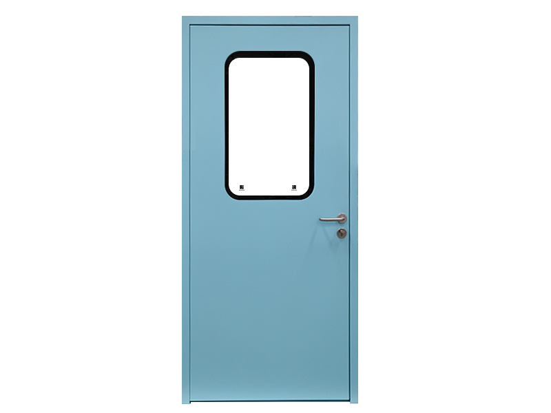
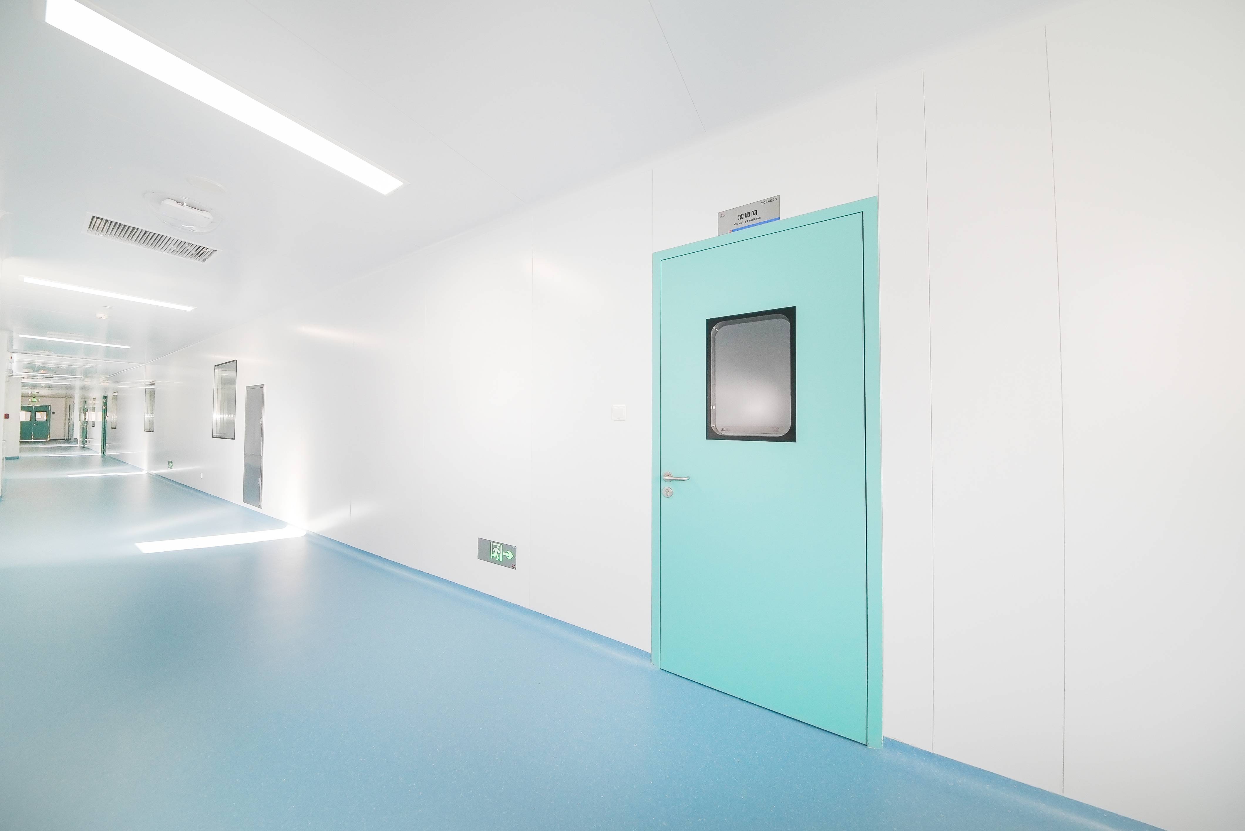
Wiskind Cleanroom specializes in cleanroom enclosure system , ceiling system, cleanroom doors and windows and related product development, manufacturing, sales, consulting and services.